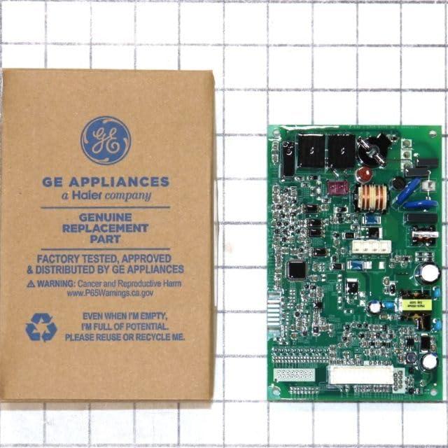
Sliding the board out of its anti‑static bag, you notice the cool, slightly gritty feel of the PCB under yoru fingertips and the modest weight as it settles in your palm. The GE WD21X29604 control board reads as compact and flat, its mass visually anchored by a cluster of molded connectors at one edge. Silk‑screened labels and tiny LEDs catch the light while solder joints glint against the matte surface, and the plastic standoffs and mounting holes show you at a glance how it will sit in the machine. Power it up briefly on the bench and the soft blink of diagnostics and a faint relay click make it feel like a small, precise machine in your hands.
What you notice first when you open your dishwasher and see the control board
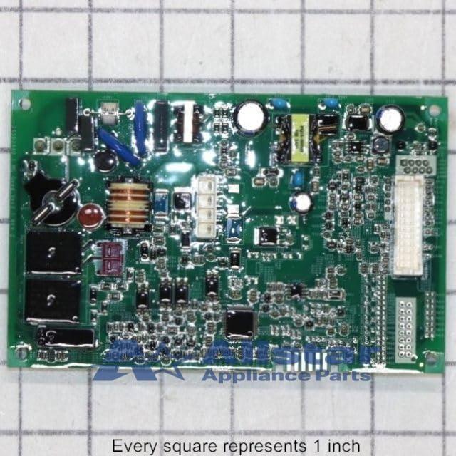
When you swing the dishwasher door open and look straight at the control board, your eye is drawn to the small, busy patch of circuitry tucked behind the inner panel. You notice wiring bundles routed into plastic sockets, a handful of larger relays and capacitors that interrupt the grid of resistors and chips, and the occasional pad of adhesive or foam holding things steady — little signs of how the board sits in daily use. A printed label or sticker on the board tends to stand out first; it’s were the row of letters and numbers lives, and it’s often the clearest thing to read without leaning in or grabbing a flashlight.
In the first few seconds you tend to register a few practical details together:
- Label and part text that you can read from a short distance;
- Connector clusters where harnesses plug in and are routed toward the door or chassis;
- Visible repairs or residue — adhesive, small scratches, or dust that suggest past handling or long-term placement.
| Observed label text |
|---|
| Dishwasher Configured Machine control board Part Number WD21X29604 replaces WD21X28418, WD21X28419, WD21X29605, WD21X29658 “isProductSummaryAvailable”:false,”device”:”desktop” Genuine OEM Part # WD21X29604 Part Number WD21X29604 replaces WD21X28418, WD21X28419, WD21X29605, WD21X29658 › See more product details |
The board in your hands: materials, finishes and how its components are arranged
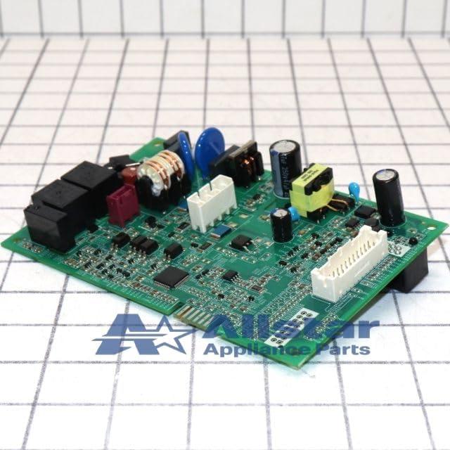
when you lift the board into your hands, the first impressions are tactile and visual: a flat, fibreglass substrate with a slightly textured solder mask, small speckles where traces and vias catch the light, and a handful of heavier components that anchor the otherwise delicate layout. You’ll notice printed identifiers and white silkscreen legends that run alongside connectors and test points, which makes identifying pins straightforward when you’re peering close. The finish around the edge connectors tends to be smoother and a touch shinier where the plating sits; other areas have that matte, factory-applied look. In use you sometimes find yourself rotating the board to read tiny codes or to line up screw holes, and the arrangement encourages that — components are grouped so related circuits sit near each other rather than scattered randomly.
- Connector clusters — ribbon headers and multi-pin plugs sit along one edge so you can orient the board easily during installation.
- Power and switching components — relays and larger capacitors occupy compact islands with visible clearances around them.
- Signal area — dense SMD components and ICs are packed closer together, with silk labels nearby for reference.
The layout reads like a workshop map: mounting holes and plastic standoffs are spaced to align with the dishwasher’s chassis, and traces run in predictable lanes rather than crisscrossing the whole surface. You can see where thermal and mechanical priorities influenced placement — heat-generating parts have a little breathing room and often sit with thicker traces beneath them. Routine interaction leaves small, ordinary marks: a fingerprint on a pin header, dust collecting in low corners, the occasional wiped smudge where you checked a label. A simple table below sums how those visible layers present themselves during handling.
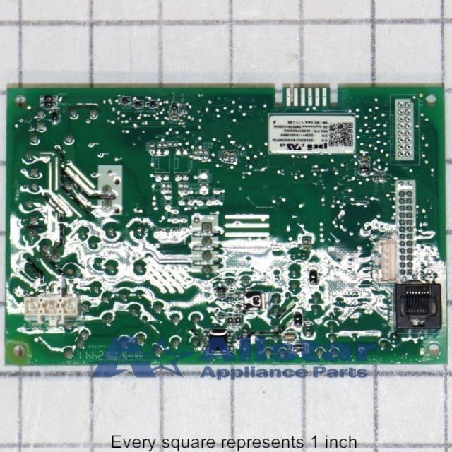
| Visible layer | What you see when handling |
|---|---|
| Substrate | Matte, slightly fibrous surface with drilled mounting holes and plated vias |
| Solder mask & silkscreen | Colored finish with white markings for connectors and test points |
| Components & connectors | Mixed SMD and through-hole parts grouped by function, with edge connectors aligned for installation |
Where it lives inside the machine and how it aligns with the mounts and connectors you access
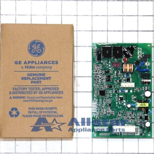
You’ll usually find the board tucked low in the cavity behind the dishwasher’s kick plate, seated against a stamped-metal bracket near the front edge of the frame. When you look in there, the board lies flat or at a slight angle so the main cable bundle runs up into the valve and pump area rather than across the tub; that orientation means many of the plugs and the screw posts you can reach without fishing deep into the machine. the replacement/compatibility note shown below is often printed in parts lists or on packing slips for reference:
Dishwasher Configured Machine control board Part Number WD21X29604 replaces WD21X28418, WD21X28419, WD21X29605, WD21X29658
“isProductSummaryAvailable”:false,”device”:”desktop” Genuine OEM Part # WD21X29604 Part Number WD21X29604 replaces WD21X28418, WD21X28419, WD21X29605, WD21X29658 › See more product details
- power harness — typically aligned so the large multi-pin plug faces downward toward the access opening.
- Pump/valve harness — often clipped to the side, routed directly to the floor-mounted components.
- Door/latched sensor connector — positioned near the front rail for straightforward reach when the door is open.
| Mount area | Access point you use |
|---|---|
| Lower front bracket | Kick-plate removal / front-facing screws |
| Side clips | Reach from under the lip or slightly to the side |
| Wire-retainer posts | Visible along harness runs, allow unplugging without moving the board |
Once you’re looking at it in place, the connectors and mounting holes tend to line up predictably: screw posts sit at the corners or along one edge, and the keyed plugs fit into a short row so you can track which harness goes where by sight. In ordinary use you might nudge a lose clip back into its retainer or sweep away lint from the surrounding cavity, and the clearance around the board generally lets you access the plugs from the front or slightly beneath the appliance without disturbing other assemblies; in most cases that arrangement keeps routine checks straightforward and keeps the harnesses from bunching up against the tub.
The dimensions and connector layout that determine how it fits during a replacement
You’ll notice the control board tucks into a shallow mounting bay behind the dishwasher’s access panel, so the way it sits is set by a handful of tabs and screw holes rather than by a broad flange. In practice that means you tend to slide it in with the harness plugs already nearby, angling the board to clear the chassis edges and then lowering it into place. The connector row is concentrated along one edge,so orientation matters: when the board is positioned correctly the plugs line up in a tight cluster and the mounting points come together without needing extra bending of the wires. There’s usually only a small amount of slack in the harnesses, so you may find yourself nudging a wire aside or feeding it through an existing grommet to get the connectors to sit straight against the mating plugs.
Common tactile cues you’ll encounter during a swap include distinct keyed plugs and a mix of clip-in and screw-down points. The following captures the typical layout as you see it in the cabinet:
- Edge connector cluster — a group of multi-pin plugs aligned on one narrow side of the board.
- Mounting tabs — two or three molded tabs that locate the board in the cavity before a fastener secures it.
- Auxiliary leads — short pigtails for sensors or switches routed toward the door or basepan.
| Connector | Typical position on board |
|---|---|
| power/main harness | Long edge, nearest chassis grommet |
| Control/display | Opposite corner or next to power cluster |
| Sensor/valve leads | Short pigtails toward lower edge |
Part Number WD21X29604 replaces WD21X28418, WD21X28419, WD21X29605, WD21X29658
How the control board compares with what you expect and where you might encounter limits in everyday service
In routine use, the control board behaves much like an unseen coordinator: it responds to cycle commands, cycles LEDs and relays in ways that track expected states, and tends to recover cleanly from short interruptions. Diagnostic indicators and relay click patterns show up during service checks, but built-in feedback can feel limited — technicians frequently enough rely on observed behavior rather than a verbose fault log. Observed limitations:
- Onboard diagnostics are brief and often require cross-checking with other symptoms to pinpoint faults.
- Electrical sensitivity shows as occasional resets or erratic behavior during voltage spikes or when exposed to residual moisture.
- Connector layouts and small locking tabs can make access fiddly in cramped installations, so hands-on handling time can increase during service calls.
Routine presence of dust or mild moisture tends to influence long-term behavior more than immediate operation, and some failure modes present slowly rather than suddenly.
| Replaces |
|---|
| WD21X28418, WD21X28419, WD21X29605, WD21X29658 |
During everyday maintenance, swapping or inspecting the board usually fits within a typical service visit, though variation among replaced variants can introduce small configuration or connector differences that lengthen troubleshooting.Cleaning attention is mostly habitual — keeping the area dry and dust-free tends to reduce intermittent faults — and routine checks for secure connections remain the most common follow-up. Full specifications and configuration details can be viewed here: Product listing and specifications.
Everyday signals to watch for while it’s running: lights, clicks and behavior you can observe
When the machine is running you’ll get most of your cues from the control panel and the way lights behave. At a glance, steady LEDs usually mark the active cycle while slow blinking tends to signal a pause or transition between stages. You may notice small status indicators for things like delay or rinse‑aid that come on and stay lit after a cycle finishes, and some lights can dim or seem softer in the evening — the panel doesn’t always shine at full brightness. If a light flashes in a repetitive pattern it can stand out against the steady indicators; those flash patterns show up as short bursts rather than long, continuous glows.You’ll also sometimes see tiny beads of water or a light sheen around the door edge after a run, a normal presence that accompanies the visible signals rather than a step to fix anything.
- Steady light — shows the active program stage.
- Slow blink — you’ll see this during transitions or pauses.
- Repeating flash — short, repeating bursts that catch your eye.
- Indicator stays lit after cycle — small, persistent LEDs for options (e.g., delay) remain on.
Sounds and small mechanical movements provide a second layer of details that you can pick up without opening the door. At start you’ll hear the door latch click and a couple of swift relay clicks as pumps and valves engage; during pumping and spraying there’s a steady hum or whirl that rises and falls with water flow. Expect occasional softer thumps as the spray arms turn and a few higher‑pitched clicks when the machine switches pumps or heaters off and on — these are brief and situational. Drainage brings a different texture, more of a gurgle or rush, and if utensils shift you might notice a light metallic rattle inside a cycle.the table below summarizes common audible cues and what they tend to sound like in everyday use.
| Audible signal | What you’ll notice |
|---|---|
| Initial clicks | Short, crisp clicks as the machine locks in and pumps start |
| Steady hum | Continuous motor or pump noise during wash and spray |
| Gurgle/drain sound | Intermittent rushing noise when water is being expelled |
| Occasional rattle | Metallic or clinking noises when items shift on racks |
How It Settles Into Regular Use
The WD21X29604 Dishwasher Configured Machine Control Board quietly becomes part of the kitchen’s background, noticed more in routine gestures than in any single moment. Over time its presence is measured in familiar clicks, the small adjustments made when loading racks, and the faint marks or dust that gather on nearby surfaces. Tucked behind a panel or near cabinet edges, it shapes the flow of daily rhythms and the habits that form around the dishwasher. After weeks and months it simply settles into routine.
As an Amazon Associate I earn from qualifying purchases. Amazon and the Amazon logo are trademarks of Amazon.com, Inc, or its affiliates. All images belong to Amazon