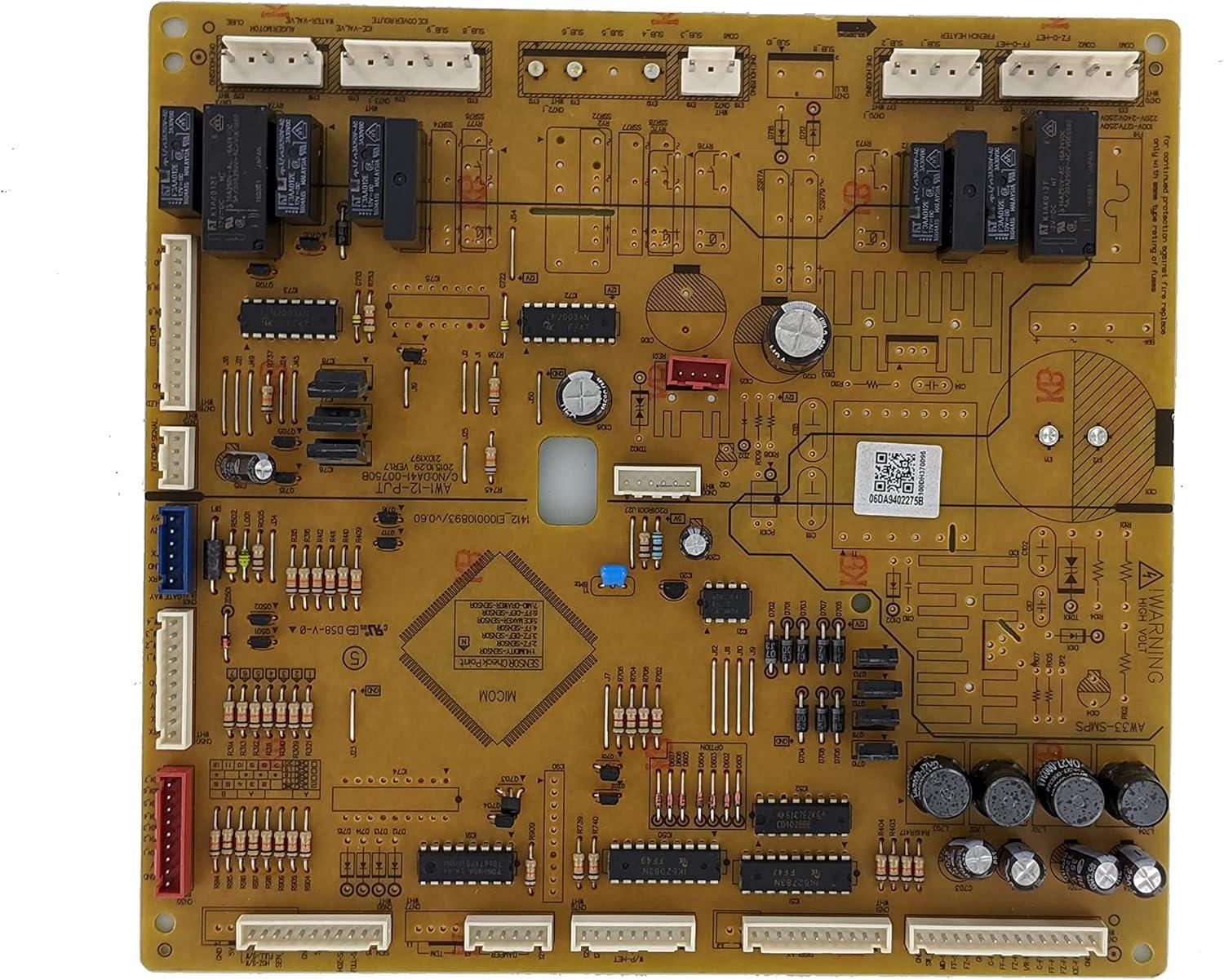
You lift the CoreCentric Remanufactured Refrigerator Electronic Control Board Replacement for Samsung DA94-02275B from its anti‑static sleeve; it’s modestly weighty — heavier than a cable bundle but not awkward, and you’ll call it the remanufactured control board for short. Under your fingers the matte solder mask has a faintly dry, tactile grain, and the plastic connectors give a small, decisive click when nudged. Brought closer, there’s a faint metal-on-insulation scent and the capacitor caps and tiny relays read like a miniature skyline under the kitchen light. Visually balanced on the counter, the brushed heat sink catches highlights without glare while printed traces and labels remain plainly utilitarian. A gentle bend makes no worrying noise; rather you notice tidy solder joints and a discreet sticker marking its remanufactured origin — small,everyday details that register before any technical checks begin.
At a glance in your kitchen: how the CoreCentric remanufactured control board looks once it’s in your Samsung
When you open the refrigerator’s access panel to check the electronics, the remanufactured control board sits tucked away rather than dominating the space — a compact circuit board behind a molded plastic housing, mounted with a few recessed screws and wrapped by the harnesses that feed into the fridge. From your viewpoint it’s mostly a patchwork of colored wires and connector plugs leading to a greenish PCB surface dotted with capacitors and ICs; a white label with a barcode and a short alphanumeric sticker is usually visible at the edge. The surrounding plastic cover and foam pads frame the board, so what you actually see during a glance is a neat cluster of components held in place rather than a sprawling tangle of electronics.
In everyday kitchen life the board is out of sight and out of mind until you lift the access cover — when you do, a few practical details stand out: clips that keep the harnesses routed along the cabinet, a modest amount of surface dust that tends to collect in corners, and the way the cover snaps back into place leaving only a small seam. You’ll notice that connectors line up in predictable locations and that the mounting points are straightforward to identify; nothing protrudes into your storage space and the plastic housing keeps the visual impact minimal. Below are rapid visual cues to look for when you inspect the area, followed by a simple reference table showing what’s visible with the panel closed versus open.
- Labeling: small white sticker or barcode at an edge
- Wiring: color-coded harnesses gathered with clips or ties
- Mounting: recessed screws and foam or plastic supports
| State | What you’ll see |
|---|---|
| Panels closed | Nothing visible — electronics concealed behind plastic panels |
| Panel removed | PCB surface, connectors, wiring harnesses, mounting points and labels |
What you notice first when you unpack it and lift it out of the anti static bag, from weight to finish and markings

When you peel the anti‑static bag away and lift the board out, the first things that register are how it sits in your hand and how the surfaces catch the light. The weight tends to feel light for a circuit board but not flimsy — there’s a slight mass where the metal heat‑sink and larger capacitors sit that reminds you it’s more than a bare PCB. The solder mask has a subdued, mostly matte look and the larger metal parts have a faint sheen; traces of flux or tiny solder rosettes are visible only if you tilt it close. The anti‑static bag sometimes leaves a soft residue or a barely perceptible plastic smell that fades quickly, and the edges where the board was tucked into foam can show minor scuffs from packing. A few immediate tactile notes:
- Weight: light overall with denser zones around heat sinks and larger components
- finish: mostly matte solder mask with isolated glossy solder joints and metal parts
- Packing signs: minor scuffs or imprinting where foam contacted the board
You’ll also focus on the printed information and stickers once the board is steady in your hands. There are multiple silkscreened legends and alphanumeric strings across the surface; connector locations and pin groupings are labeled in small text, and a separate adhesive label usually carries a short barcode or batch number you can read without a loupe. Inspection stamps or tiny ink dots from quality checks are often near the corners or along the mounting holes, and component identifiers (R, C, U, J) are clear enough to trace with a quick visual scan. The simple table below summarizes the kinds of markings you can expect to see at first glance:
| Marking | Typical appearance |
|---|---|
| Part/ID legend | Silkscreened alphanumeric string or printed label on the board |
| Date/revision code | Small stamped or printed code near the edge or connector area |
| Connector labels | J‑, P‑ or CN‑style silkscreen identifiers beside each plug |
| Inspection/stamp | Ink dots or tiny stickers near mounting holes or test points |
The plastics, PCB work and connector details you can examine up close

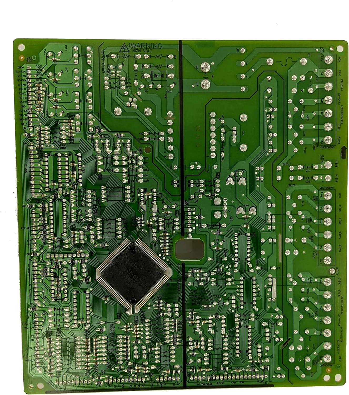
When you handle the unit up close, the molded plastic shell reads like typical injection-mold work: a matte, slightly tacky surface on the outer face and glossier inner ribs where the mold separated. You’ll notice molded screw bosses and thin snap tabs that let the cover latch to the chassis; they flex a little when you disengage them and tend to show tiny scuff marks from repeated removal.There are visible parting lines and small ejector-pin marks in discreet places rather than across prominent faces,and the openings for the wire harness have rounded strain-relief lips rather than sharp cutouts,which is the detail you’ll feel when routing cables. Routine checks usually involve a quick visual sweep for dust in crevices and a wipe of the exposed faces; you’ll sometimes find a trace of assembly residue near recesses but nothing that obscures the mounting geometry.
Pull back the cover and the board itself presents a tidy mix of surface-mount and through-hole components, with clear silkscreen labels that help you spot connector keys and test points. Solder joints look uniform along the larger pins while the finer SMT joints sit low and densely packed; in some places a thin conformal coating covers sensitive areas,so you’ll see a subtle sheen rather than bare copper. The connector housings are keyed and have small retention ramps you can feel when seating harnesses; the diagnostic header is exposed for quick probing and the main power connector aligns squarely with its mating plug. Observations you might make at a glance include:
- main harness connector — large, keyed, with a tactile latch ramp
- Auxiliary signal plug — smaller, close-tolerance pins, snug fit
- Service header — open pins, labeled silk nearby
| Connector | Board area | Notable detail |
|---|---|---|
| Main harness | edge near mounting boss | keyed housing, retention ramp |
| small signal plug | center cluster | tight pin spacing, silkscreen ID |
| Service header | adjacent to diagnostic silk | exposed pins for quick access |
How it sits in the control housing, lines up with the mounts and takes up space behind the display
When you lift the control housing and guide the replacement board into place, it settles into a shallow channel behind the display rather than floating freely. The board tends to want the same orientation every time: the row of connectors faces the harness opening and the plastic mounting posts slip into their molded holes with a light nudge. in practice you’ll often make a small, deliberate push or slight twist to coax the posts fully home; once the board seats it feels anchored by the housing’s inner lip and the bezel that closes over it.The harness plugs line up along a single edge, so you’ll notice most of the final adjustment comes from getting that edge parallel to the display before you press the board down into the mounts.
- Standoffs — the molded posts fit into corresponding holes and usually require only light alignment.
- Connector row — this is the reference edge you use to align the board with the harness opening.
- Display aperture — the bezel sits close to the top components, so routing and clearance matter during reassembly.
Behind the display the board occupies a compact, shallow cavity; components don’t leave much room for extra wiring or bulky clips, so you’ll often rearrange a loose harness or trim a zip-tie to avoid pinching when the bezel goes back on. The proximity to the display means you can feel how snug the fit is while you lower the fascia — there’s usually a small, usable gap rather than a large air space, and that gap is where dust and occasional crumbs collect over time. During routine checks you may find yourself nudging the board slightly or re-seating a plug after closing the housing, which is part of how it behaves in everyday handling rather than a one-time quirk.
How this board measures up against your repair needs and where expectations meet real world limits
In hands-on repair scenarios, the remanufactured control board generally performs the core task of restoring electronic control functions — responses from the front panel, command signals to temperature circuits, and timing for defrost operations are commonly observed to resume once the board is installed. Installers note that the part typically mates with the existing harness layout, but modest, situational adjustments can occur at the moment of fitment: connectors occasionally need a firmer seating than expected, and small alignment nudges of mounting tabs happen in many swaps. It addresses failures that originate within the control electronics, while faults stemming from the sealed system, compressor, or wiring elsewhere in the appliance often remain and can produce recurring or intermittent symptoms even after the board is changed; the remanufactured origin also means that long-term behavior can show slight variability in a few cases.
On-install observations
- Connectors tend to require deliberate, tactile seating rather than a light push.
- labeling and sticker placement can differ from the original, which may make orientation checks useful during mounting.
- Physical fit usually lines up but sometimes needs a small repositioning of clips or screws.
Routine presence of the board in the control cavity calls for occasional visual checks for dust and secure connections as part of normal appliance maintenance rather than intensive servicing. For full listing details and available technical variants, see the complete product listing.
Everyday handling after installation: plugging connectors, routing wires and the small quirks you will live with
You’ll notice the moment you reconnect power that the board’s plugs are keyed and give a firm, tactile engagement — many of them settle with a soft click rather than a fragile snap. When you plug or unplug harnesses in everyday handling the display or controls can flash briefly as systems reinitialize; that tends to be normal and happens most often with the larger multi‑pin connectors. Some plugs look very similar at a glance, so you may find yourself pausing to check orientation before seating them; once they’re in place they feel secure, but a couple sit very close to the sheet‑metal edges and can seem slightly pinched when the rear access panel is refitted. In routine use you might re-seat a connector now and then if a control behaves oddly, and those small reseating moments are part of the appliance’s lived behavior rather than a sign of something dramatic.
Wire routing around this replacement board follows the same patterns you already live with: harnesses are long enough to loop, and most people end up tucking the excess behind brackets or into a shallow bend rather than trimming anything. A few small quirks show up over weeks of use:
- Closely packed plugs — a tight cluster near the edge of the board can make one‑handed access awkward.
- Slack loops — extra wire tends to form a loose arc that you’ll see behind the control panel if you peer in.
- Faded labels — the silkscreened markings are useful but sometimes faint,so you rely on connector shape more than printing.
Those little things affect how you move the panels and where you rest your hands during quick checks; they also determine whether you clip a spare tie in place or simply tuck a lead out of sight. dust collects in the same spots it always has,and the presence of the new board doesn’t change the routine of the occasional glance behind the panel to make sure nothing has shifted.
A Note on Everyday Presence
The CoreCentric Remanufactured Refrigerator Electronic Control Board Replacement for Samsung DA94-02275B quietly takes its place behind the access panel, showing up in the small rhythms of the kitchen more than in big moments. In daily routines it is indeed noticed by steady patterns—the fridge light, soft clicks, the way temperatures settle—and the surrounding plastic and metal pick up the occasional fingerprint or screwdriver nick that marks a life lived in the space. It shares room with magnets, grocery lists, and the habitual opening of the door, blending with worn surfaces and everyday motion until it feels ordinary. Over time it simply settles into routine.
As an Amazon Associate I earn from qualifying purchases. Amazon and the Amazon logo are trademarks of Amazon.com, Inc, or its affiliates. All images belong to Amazon