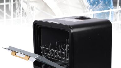
You lift the replacement board from its foam tray and notice the surprising heft — flat and compact, but weighty in your hand. The Hobart CNA/CCA200 main board (897545-004) catches the light with a thin, slightly glossy film that feels a little tacky under your fingertips, the kind of finish that suggests moisture protection. As you pass it back and forth the connector rows seat with a soft, precise click and the solder joints look clean and purposeful; visually it sits low and tidy, more engineered tool than decorative part, quietly at home on your workbench beside the dishwasher.
When you lift the Hobart service panel: how the compatible CNA CCA200 main board presents itself

When you lift the Hobart service panel,the main board sits framed behind a shallow metal bay so it’s immediately obvious how densely things are arranged. The PCB carries a slightly glossy film that catches the light — a conformal coating that tends to make the board look a bit wet or plastic-coated at a glance — and you can pick out relays, a few electrolytic capacitors, and a handful of terminal blocks by their shapes rather than by reading tiny print. Wires run into keyed plastic connectors grouped along the edges, and several connectors are color-banded or tied with short harnesses so their routing looks deliberate.Small LEDs and silkscreened labels sit near the edge of the board; they’re not intrusive but they give you quick visual checkpoints when you’re peeking in during a routine service moment.
As you handle the cover and lean in, tactile cues become as informative as sight: many plugs require a slight press or angle to release, mounting screws hold the board solidly so it doesn’t flop when you move a connector, and thin foam or a gasket around the cavity shows where moisture control was considered. You’ll notice residue and dust collect in the corners in most units, and the conformal layer usually stops short of connector pins so solder joints remain visible. A few simple, visible groupings help you parse the layout without a schematic — power components clustered on one side, control circuitry on the othre — and small protective shields or clips are used where wiring crosses. below are quick visual cues to look for while the panel is open, followed by a short descriptive table.
- Conformal coating: glossy sheen on component surfaces, not always uniform
- Connector clusters: keyed, color-banded harnesses along board edges
- Mounting points: accessible screws and brackets that hold the board steady
| What you see | Practical note |
|---|---|
| Glossy coating over circuit area | Visible protection layer that can obscure fine corrosion but leaves connector pins exposed |
| Grouped connectors and harnesses | Color and keying make tracing wires quicker during a casual inspection |
| Clustered power components | Heavier parts are placed together, making heat and clearance visually evident |
When you pick it up: the arrangement of components, solder joints and the tactile impression of the board and housing
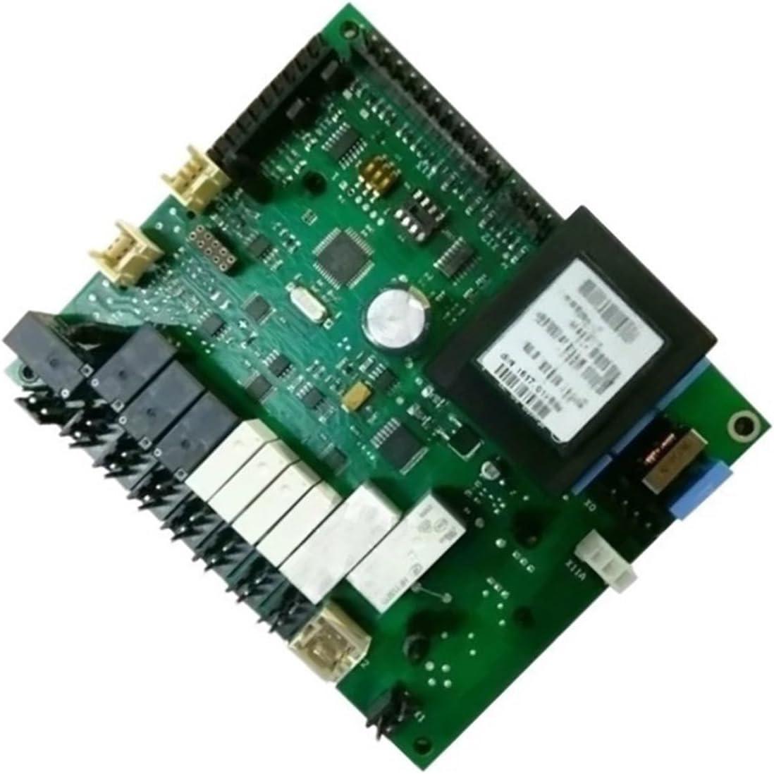
When you pick it up, the arrangement reads quickly under your fingers: larger capacitors and relays sit toward one edge, while the control ics, resistors and power transistors form a tighter cluster in the centre. Connectors and header pins run along the perimeter so your hand tends to land on the board’s edges rather than on components, and the mounting holes give predictable contact points when you shift the board for inspection. The solder joints are visible at a glance—most form smooth, rounded fillets with a consistent sheen, and a few areas show faint flux residue around pin rows. The overall spacing gives you clear visual cues about power paths versus signal areas, and the populated and unpopulated zones are easy to distinguish. A few tactile and visual cues you’ll notice up close include:
- Component clusters: distinct groupings that make it easy to follow functional areas with your eyes or a fingertip.
- Solder texture: generally smooth fillets; small spots of residual flux in tighter pin arrays.
- Connector fit: headers seat flush and bark a soft click when aligned, so you can tell engagement by feel.
With the housing in place the impression shifts: the plastic frame gives a firm, slightly hollow feel and the snap-fit tabs compress with subdued feedback when you handle the assembly.The conformal coating appears as a thin,glossy veil over many components—under your thumb it can feel a touch slick but not tacky,and it tends to blur fine surface detail while leaving the solder beads clearly visible. The board doesn’t feel heavy; it sits with minimal play on its bosses and the edges of the housing have a fine matte texture that resists fingerprints. Over time you’ll observe dust collecting in connector recesses and around screw bosses during casual checks rather than during routine handling.
| Area | Visual / Tactile note |
|---|---|
| Power cluster | Spaced apart, warmer-coloured components, larger solder pads |
| Connector edge | Flush seating, audible/ tactile click, slight recesses for wiring |
| Coated surfaces | Thin glossy finish; smooth to the touch, reduces visible texture |
How it fits inside your machine — mounting holes, cable reach and the clearances you’ll have to work around
The board’s mounting holes are arranged so the PCB sits flush against common dishwasher standoffs, and in practice that means the fastener points tend to line up with the cabinet ribs rather than with flat sheet areas. Mounting holes are best thought of as alignment guides: they keep the board off metal surfaces and centered under the control fascia, but they rarely give several millimetres of play, so small shifts of the chassis or bent tabs can force a slight rotation of the PCB during installation. connectors that plug into the board sit along one or two edges, so the board often must be eased into position with the harnesses already supported; routing the harnesses first and then lowering the board into the standoffs reduces tension on the pins.Typical on-the-bench behavior is to nudge the board into place, secure a single screw to hold it, then finish the remaining fasteners once the cable runs have settled into their channels.
Clearances around the board influence routine interaction more than precise measurements do. The space between the control panel and the PCB should allow room for the largest connector to be seated and removed without excessive bending; ribbon cables and multi-pin plugs need gentle curves rather than sharp turns and tend to be the tightest constraint. Nearby components such as the water inlet valve, pump housing or thermal cutouts can block access from one side, so installers often approach the board from the access panel opening rather than trying to work through smaller service holes. The table below outlines common obstruction points and what to watch for during a fit check.
| Area inside the cabinet | Practical clearance note |
|---|---|
| Under control console | Allow space for connector engagement and occasional visual checks |
| Beside pump/sump | Keep cables tucked away from moving parts and heat sources |
| Rear chassis near inlet | Leave slack for strain relief and to accommodate service removal |
- Mounting holes: tend to fix orientation—plan for minor alignment work.
- Cable reach: multi-pin power leads usually require the most slack; sensor and switch wires can be routed more tightly.
- Access space: a small gap for finger clearance makes connector work less fiddly during routine checks.
View full listing and configuration details on Amazon
The hands-on rhythm of installation and access: what you do with your tools and where your fingers meet the connectors
When you clear the lower access space and bring the board into view, most of the tactile story happens in a few small motions: your fingertips searching for keyed housings, a thumb pressing a latch, a slight twist to free a connector that sat recessed behind a clip. The connectors themselves tend to offer clear feedback — a soft give, then a firm click — and that rhythm guides how you work, faster when things seat easily, slower when a pin resists. You notice the difference between broad plastic plugs that you can palm and the narrow multi-pin sockets that demand fingertip precision; sometimes you find yourself angling the board a fraction to line things up, pausing to feel for alignment rather than watching the light. Wearing thin gloves changes the cadence; you trade a little sensitivity for cleaner hands and may rely more on visual cues if the click is muted by a sleeve or a cold, stiff finger.
Tools tend to accompany those hand movements but rarely dominate them: a short screwdriver to free a retaining plate, a flashlight tucked under a lip, needle-nose pliers for coaxing a stubborn tab. In routine reassembly you find yourself doing a few habitual checks with your hands — tucking harnesses so they don’t snag, testing strain-relief seating, and wiping nearby contacts with a cloth as part of the general clean-up. A brief list of the small, recurring tactile cues you rely on might include:
- feel for keyed orientation — you sense when the plug won’t fit a certain way
- listen for the click — that sound confirms engagement more than a glance
- check strain relief — the harness should sit snug where it exits the housing
| Action | What you feel |
|---|---|
| Seating a multi-pin connector | Light resistance then a subtle snap |
| Removing a keyed plug | A short pull with a release tab that gives way |
signals in everyday operation: the lights, connector behavior and patterns you’ll observe while it runs
When the dishwasher powers up you’ll notice a short, predictable sequence of lights rather than a single static glow. A solid power LED or panel icon usually comes on first, then one or two cycle indicators will flash briefly as the control board runs its initial checks; during the active wash phase one indicator tends to stay steady while others pulse or alternate to show progress. you may also catch moments of faint flicker or a brief blackout of display elements when pumps or valves kick in — it’s common for indicator brightness to change in sync with mechanical events. Small button backlights and touch indicators respond instantly to taps, and during drying or heating cycles the corresponding light can shift to a different color or adopt a more rapid blink pattern you’ll learn to read over time.
You’ll also observe subtle connector and behavior cues while it runs: harness plugs make a soft click when latched and remain visually settled, but slight movement at service access points can coincide with transient display glitches or a momentary pause in cycle-indicating lights. In everyday use this looks like a brief reset of a progress LED or an alternating blink sequence that clears after a few seconds. The table below shows common, straightforward patterns you’re likely to see and how they present; keeping the connector areas free of obvious debris as part of routine checks helps them keep that steady, predictable behavior.
| Event | Typical LED/Panel Behavior | What you’ll notice |
|---|---|---|
| Power-up | Short sequence of steady and flashing lights | Lights come on in order, then settle |
| Wash/pump start | One light steady; others pulse or dim briefly | Subtle flicker or change in brightness |
| Heating/dry | color shift or faster blink of heater indicator | Panel glow feels warmer/brighter |
| Intermittent contact | Transient blinks or reset-like flashes | Lights jump then return to normal after a moment |
How this compatible main board aligns with your expectations and the practical limitations you may encounter
In routine operation the replacement main board tends to settle into familiar patterns: program cycles start and finish with the same cadence as the original control unit, and the dishwasher’s responses to mode changes feel consistent. During normal runs the board’s diagnostic LEDs and self-test sequences are noticeable but not obtrusive; small differences in light intensity or the length of the startup check can appear, yet the overall sequence control and motor/pump transitions remain steady. Because the module lives in a confined, humid space, most interactions are observational rather than hands-on — visual checks often reveal whether contacts sit cleanly and whether any condensation has been an issue, and the unit’s presence rarely changes day-to-day use beyond those occasional looks.
Practical limits become apparent around access and diagnostics. Physical access to mounting points and connectors can be tight, so tasks that involve inspecting the board tend to take a bit more time than expected; seating of plugs and the neatness of wire routing show up as recurring, low-level concerns. diagnostic differences — slightly altered LED patterns or error-code behavior — can make comparing symptom histories across repairs less straightforward. For upkeep, routine visual inspections and leaving panels accessible for occasional checks are the most common interactions rather than frequent maintenance. Full specifications and configuration details can be consulted here.
Scale and storage: the board’s footprint, measurements and how it sits beside other spare parts in your kit
the board lies flat and takes up a modest rectangular area that most technicians will recognise as occupying a shallow drawer or a single foam cavity rather than a deep bin. In everyday handling it tends to be treated like other flat electronics: usually bagged in anti‑static film, laid on a shelf, or slid between larger assemblies. Because connector housings and a few raised components protrude slightly, stacking it directly on top of other parts is done with a bit of care; incidental contact with nearby relays or small motors is common unless foam separators are used. typical kit neighbors:
- wire harnesses and terminal blocks
- control panel overlays and buttons
- small relays, thermal fuses and door latch assemblies
Seen side‑by‑side with those items, the board most often occupies the “flat, fragile” slot in a parts case rather than the compartment for bulky mechanical pieces. In practical terms it sits better alongside other circuit boards or in a shallow compartment of a larger organizer; its depth is usually less of an issue than the need to protect connector pins and solder points.The table below gives a simple contextual comparison of how it tends to be stored relative to a few common spare parts (dimensions are indicative for spatial planning, not technical specification):
| Component | How it typically sits in a kit |
|---|---|
| Main control board | Lays flat in anti‑static bag or foam cavity; stacked with similar boards |
| Door latch assembly | Often stored upright or in a deeper compartment due to bulk |
| Relay pack / small motors | Placed in small boxes or dividers to avoid contact with PCB protrusions |
Complete listing facts and specifications can be examined here.
Its Place in Daily Routines
Living with the compatible with Gundam Compatible with Hobart dishwasher accessories CNA CCA200 Main board 897545-004 over time, you find it folding into the kitchen’s background rather than standing out.Its plastic and metal surfaces pick up the faint smudges and tiny scuffs that come from regular handling,and you move around it without pausing. In daily routines you reach for it the same way, its presence registered in small habits and repeated motions. After some time it simply settles into routine.
As an Amazon Associate I earn from qualifying purchases. Amazon and the Amazon logo are trademarks of Amazon.com, Inc, or its affiliates. All images belong to Amazon