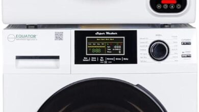
You lift Allstar Appliance Parts’ WPW10384849 washing machine motor control board from its box; the first impression is a modest heft — not fragile, not bulky. The board’s matte PCB is cool and slightly grainy under your fingertips, and the plastic connector housings click with a purposeful stiffness. Under the worklight the solder joints and traces pick up a soft sheen, and once its seated behind the access panel a faint relay click is the first audible sign of life. Visually it reads as compact and orderly, components laid out with a balance that makes the whole feel engineered rather than improvised.
Seeing the WPW10384849 in your washer: the first glance that starts a repair

When you crack open the access panel and look in, the control board is one of those components that immediately registers as “the electronics” — a flat rectangle mounted to a bracket, with bundles of colored wires leading into it and a handful of plug‑in connectors lined up along one side. Your eye tends to catch any white or silver sticker first; it usually carries a printed number and a small barcode, and the placement of that sticker helps you orient the board without having to trace every wire. Around the board you’ll see the hardware that holds it in place, the way the harnesses loop toward the motor or power feed, and the larger components (relays, coils, a few capacitors) that sit noticeably taller than the rest of the circuitry. Small details — a bent mounting tab, a connector pushed slightly off its seating, a patch of darkening on the plastic — show up quickly when you’re standing there under a workshop light.
Several quick visual markers tend to frame that first look:
- Label and markings — a sticker or silkscreened text that gives a readable reference point
- Discoloration or melting — darker PCB areas or warped plastic near high‑heat parts
- Connector seating — how snugly the wire blocks sit and whether any pins are exposed
| Visible item | Where you’ll usually see it |
|---|---|
| Sticker/part text | Along an edge or near a mounting screw, often the easiest reference |
| Wire harnesses | Grouped into colored bundles heading toward the motor, pump, or power input |
| Signs of heat or residue | Darkened areas, slight charring, or melted plastic around high-current components |
Dust, lint, and occasional surface grime are often present too, settling where airflow is restricted; those everyday residues can make small stains or mineral streaks stand out more than they would on a cleaner board.
What you notice when you lift it out: weight, finish and the stamped part details
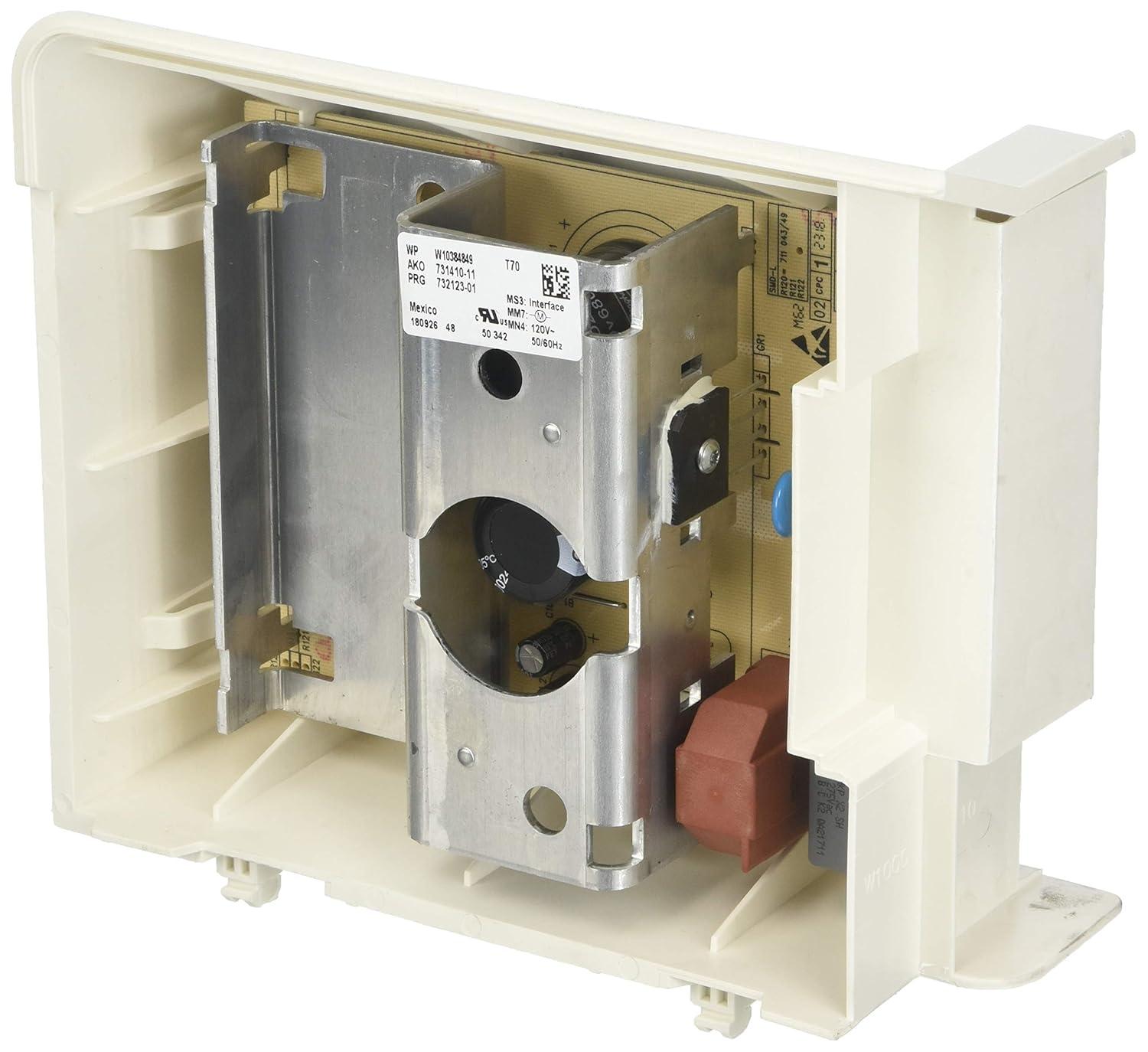
When you lift it out, the first thing you notice is the way it balances in your hand: it can feel lighter than the idea of a “control module” suggests, largely because most of the mass is a thin printed circuit board with a few denser components and a small metal heat spreader. The housing and connector block give the piece a compact, flat profile so it doesn’t feel bulky as you move it; simultaneously occurring, the weight distribution tends to be toward the side with the larger capacitors and relays. The plastic edges are slightly textured and the molded mounting tabs have a matte finish, while solder joints and metal terminals catch the light with a dull sheen. Connectors are keyed and a bit stiff at first — you’ll often nudge them free with a small wiggle — and you may notice dust or faint fingerprints on exposed metal surfaces, the sort of everyday residue that suggests occasional wiping during routine maintenance rather than deep cleaning.
Stamped and printed markings are easy to spot once you hold the board up to the light: there’s usually a silkscreened identifier, a small sticker with a production code, and a few laser-etched numbers along an edge or near mounting holes. You’ll see a mix of bold, readable characters and finer revision codes or batch numbers that require a closer look. The table below shows the types of markings you commonly encounter and what they look like in situ.
| Marking | How it appears when you lift it out |
|---|---|
| Part code | Printed in white on the PCB or on a small adhesive label, usually the most prominent string of letters/numbers |
| Revision/Letter | Single letters or short codes near component clusters, sometimes faint or overlapped by manufacturer’s ink |
| Date/batch code | Smaller numeric strings, often on a sticker or laser mark close to an edge or connector |
| Manufacturer mark | Tiny logo or factory stamp, occasionally accompanied by a handwritten dot or inked check from final inspection |
- Legibility: most markings are immediately readable; a few require angling the board or better light.
- Placement: identifiers cluster near mounting points and connectors rather than across populated component areas.
How it sits and connects inside the cabinet: clearances, mounting points and cable reach you’ll contend with
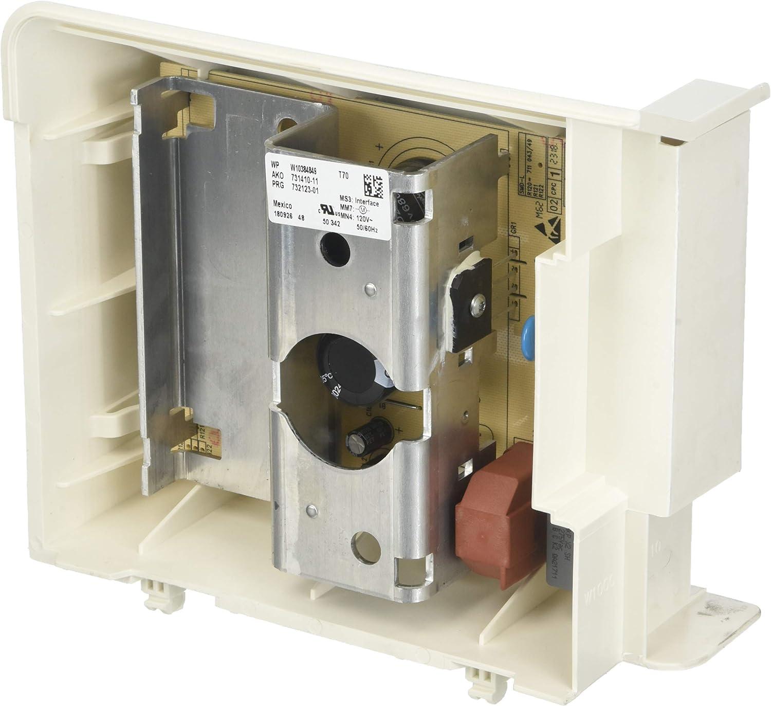
The control board mounts low and tucked behind the machine’s access panel, sitting against a metal chassis bracket with two or three screw posts that line up with factory holes. Clearance around it is often modest: there’s usually just enough room for a hand and a small driver, and nearby components — the motor housing, drain pump, and bundles of harnesses — can feel crowded in tighter cabinets. In practical terms, the critically important observations are these:
- Mounting points — fixed screw bosses are in predictable locations and tend to accept the same fasteners used on original boards.
- Nearby obstructions — hoses and the tub edge may run close, so the board sits in a shallow pocket rather than an open bay.
- Working clearance — access usually requires the lower panel to be removed and some lateral reach to manipulate screws and connectors.
These conditions mean the board rests flat against the chassis and usually doesn’t float free; minor nudging of adjacent wiring or brief repositioning of a hose is a common part of installation or inspection in most setups.
Connectors arrive on short, keyed harnesses that plug directly into the board; a main multi‑pin harness and one or two smaller motor/sensor leads are typical.The orientation of those plugs determines routing tightness — when routed around the motor or under support brackets, the harnesses can feel snug and may require a small amount of re‑routing to avoid strain on the plastic housings. A simple reference table shows the common connector layout and typical routing notes:
| Connector | Typical location | Routing note |
|---|---|---|
| Main multi‑pin | Top/side edge of PCB | Routes to the control harness bundle; fits closely to chassis. |
| Motor lead | Near board edge | Frequently enough runs toward the motor housing; can be tucked under a clip. |
| sensors/switches | Small 2–4 pin plugs | Short reach; routing follows the cabinet seams. |
Full specifications and variant details are available on the product listing: View listing
How the WPW10384849 lines up with your repair expectations and the practical limits you’re likely to face
In everyday repair work,this control board tends to behave like a straightforward electronic swap: when it mates cleanly with the existing harness and mounts in the expected location,cycle control and symptom resolution often follow quickly. Observers note, however, that several practical limits turn up during routine installs. Most commonly, the issue isn’t the board itself but how it interacts with the rest of the appliance—loose wiring, damaged connectors, or unrelated mechanical failures can leave a swapped board appearing to underperform. These tendencies show up not as product claims but as real-world patterns technicians encounter on the bench and in-service calls.
- Compatibility caveat: replacement identifiers generally match, yet connector orientation or harness routing can be awkward in some chassis layouts.
- Access and timing: cramped interior space and obstructions sometimes extend a swap beyond a quick session.
- Environmental wear: corrosion or residue in the machine environment can limit long-term behavior even after the control board is replaced.
The board typically settles into the role of controlling cycles without ongoing attention, occupying a tucked-away position behind the console where routine maintenance is minimal; occasional visual checks during other servicing are the usual interaction. Repair times therefore tend to cluster around a single service visit in many cases, though hidden damage or unexpected wiring faults can prolong troubleshooting and make outcomes less immediate. Full listing information and the complete specification set can be examined on the product page here.
The routine checks you carry out after fitting and the visible signs you watch for during the first cycles
Once you’ve refitted the board and run the first cycles, you mostly watch and listen rather than tinker. At power-up you notice whether the machine settles into its usual rhythm — lights on the console behaving normally, the door/lid engaging with a single click, and the drum beginning to move without sudden judders. You pay attention to any new or unusual sounds: a steady hum that stays consistent, intermittent clicks as programs change, or a high-pitched whine that wasn’t there before. Visible signs you keep an eye on include puddling or wetness around hose connections and the base, any darkening or scorching near the control area, and the way the cabinet vibrates against the floor during spin. You also look for unexpected display behaviour — flashing codes, unusually short or long cycle times — as part of those first runs.
- Noise: pattern and consistency of hums, clunks, or squeals
- Vibration: wobble, cabinet movement, or items shifting nearby
- Leaks: damp seals, drips under the machine, or pooled water
- Smells/visuals: burning odour, smoke, discoloration near connectors
- Display behaviour: error flashes, program timing, unexpected stops
You also make a few quick visual checks between cycles as part of settling in: an unobstructed wiring loom at the back, the control board area free of obvious moisture or lint build-up, and any connectors that sit flush rather than tugged at odd angles. over the first handful of loads you note whether cycle characteristics — fill, agitation, spin duration — feel consistent with what they were before; small, momentary variations tend to occur, while repeated changes or recurring error indications stand out. The tiny table below is a concise reference of the kinds of signs you frequently enough correlate with common observations during those early runs.
| Visible sign | How you typically interpret it |
|---|---|
| Intermittent clicking | Relay or cycle switching that shows timing changes but is often momentary |
| Sustained humming | Motor load or stalled movement that you notice when spin feels heavier |
| Repeated error codes or stops | Electrical or connection issues that recur across several cycles |
A Note on Everyday Presence
Over time the WPW10384849 Washing Machine Motor control Board fades into the backdrop of the laundry room, its soft clicks and pauses becoming part of the room’s regular soundscape. In daily routines its presence shows up in small behaviors—how loads are timed, how the space is arranged—and on the surface a few faint scuffs or dust traces mark ordinary use. It sits against shelves and cords,fitting into the flow of chores and easy habits,familiar in a way that makes it unremarkable. It settles into routine.
As an Amazon Associate I earn from qualifying purchases. Amazon and the Amazon logo are trademarks of Amazon.com, Inc, or its affiliates. All images belong to Amazon